
News
New Principles of IMA System Implementation Based on Fastwel CPB906 Mezzanine COM Module
17.07.2014
Consideration here is given to Fastwel experience in designing modules in 3U VITA 46/48 format with PCI
Express interface for the use in the scalable crate, as well as to peculiarities of the CPU module implementation
with PCI Express system bus on the basis of Fastwel CPB906 mezzanine COM module with PCI.
Introduction
Systems based on the Integrated Modular Avionics (IMA) concept, are intensely developed for use in the modern avionic
equipment.
The IMA system is a crate with backplane, which connectors are used for standard standalone modules. Repair and routine
maintenance of these crates is achieved by separate modules prompt replacement, which makes it more comfortable to
perform maintenance and repairs as well as enables cutting operating costs. Moreover, the use of standard parts and
connectors reduces manufacturing costs.
The R&D company “Elara” has developed the crate of avionics indicator console in 3U VITA 46/48 format based on Vortex86DX processor board CPB906. The structure of
VITA 46/48 crate is designed for operation in harsh environment, and at the same time – for using modern high-speed data exchange protocols and provision of
electromagnetic compatibility.
System purpose and functions
Indicator is intended for displaying video in ARINC 818 format which is transmitted via two optical channels. The system is controlled by the built-in protected keyboard.
The onboard information is transferred via ARINC 429 interface and the software is updated via Ethernet channel. The indicator also receives 8 input and generates 8
output one-time commands, including integral proper functionality of the system.
Choosing CPU Module
Based on technical specification requirements, the indicator should not only display the received video data, but also add textual and graphic information to the video
and the high-speed input video channel enables transferring large data quantities within the system, therefore a serial high-speed PCI Express (PCIe) bus has been
chosen as the system bus.
However, it was hard to determine the right design of 3U CPU module based on PCI Express bus. Using ready-made CPU boards in 3U VITA 46/48 format in their
proprietary crates produced by other local manufacturers, proved to be inappropriate: despite the standard VITA 46/48 design. Each developer chooses system bus
and other interfaces which meet minimum requirements for solving specific tasks of their systems, for which reason various 3U VITA 46/48 CPU modules may be
incompatible.
This required developing the CPU module installable into 3U VITA 46/48 crate. The module provides the following functions:
1) Inter-module high speed data exchange within the crate over the PCI Express 1x bus via backplane (number of target devices – 2);
2) Processing of interrupt requests from target devices (single-function target devices, number of interrupt request lines: 1 from each device);
3) Data exchange with external devices as part of integrated onboard equipment via 100 Mb/s Ethernet (IEEE 802.3) channel which can also be used for updating of functional software.
4) Hardware support of USB interface with possibility to load from flash-drive;
5) RS-232 support;
6) Loading of Linux-type operating system takes no more than 40 seconds, which provides a short ready-to-operate period for the whole device after power ON/OFF.
![456197$[250x250].jpg](/upload/medialibrary/494/456197$[250x250].jpg "456197$[250x250].jpg")
Fig.1 Indicator with crate structure
![456207$[250x153].jpg](/upload/medialibrary/86c/456207$[250x153].jpg "456207$[250x153].jpg")
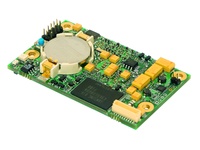
Fig.2 CPB906 Module
7) Storage and loading of system and functional software, integrated flash-drive;
8) Debugging mode, video output to monitor and input for the connection of PS/2 keyboard.
In addition, the module should guarantee operation in harsh environments and the most crucial requirement here is the ability to operate in the extended temperature range.
In order to meet customer requirements it was decided to install Fastwel mezzanine CPU module into the carrier board. The carrier-board for 3U module has the following dimensions: 100x171 mm. Fastwel CPB906 CPU module, shown on Fig.2, has been selected as the mezzanine board. It has no integrated PCI Express interface but as for the rest functionality it perfectly corresponds to the set requirements¹. For transferring command data, PCI bus bandwidth capacity would be enough and the carrier board has the installed PCI-PCI Express bridges made by PLX Technologies in order to arrange inter-module data exchange via PCI Express bus.
CPB906 CPU module is a system on module (SoM), which offers a high performance and at the same time low power consumption and low heat dissipation. Industrial version of the CPB906 module has an extended operating temperature range: –40…+85°С.
Key features of CPB906 CPU module
| CPU | Vortex86DX |
| Operating clock frequency | 600 MHz |
| Architecture |
- 32 bit x 86 core - 16 bit memory bus |
| Memory | |
| RAM |
256 MB DDR2 SDRAM 256 Byte internal memory |
| Integrated nonvolatile memory | 8 Kb FRAM (SPI) |
| Flash-drive | 1 GB NAND Flash (SLC) |
| Ports | |
| LAN-Ethernet | 10/100 Mb/s (MAC +PHY) |
| USB (host) | 2x USB 1.1, USB 2.0 ports |
| COM1, COM2 | RS-232 (TTL levels, 5x wire) |
| GPIO |
- 6x digital I/O channels - 2x channels of integrated address decoder (addressable I/O or memory space ) |
| Software compatibility with OS |
– FreeDOS, Microsoft MS-DOS 6.22 – Microsoft Windows CE 5 – Linux 2.6 – QNX 6.4x |
| Dimensions | 65,2 x 40,2 x 10,5 mm |
| Input voltage | 5 V |
| Current consumption | 450 mA |
Moreover, х86 CPUs are compatible with applications. The CPU has a wide range of interfaces: ISA, PCI, IDE 2×SDIO, 2×USB 2.0, Ethernet 10/100 Mb/s, I2C, 2×RS-232 (TTL), GPIO. Table 1 contains key features of the CPB906 CPU module.
Block diagram
The block diagram of the carrier board with CPB906 module is shown on Fig. 3. Parallel PCI bus of CPB906 CPU module is used for data exchange with two PCI Express 1х boards via PEX 8112 bridges and for output of video data via PEX 8114 bridge in PCI Express 4х format for an external graphics card. Video output is used for programming and system debugging and is routed to the additional (test) connector of the carrier-board, PS/2 keyboard ports, USB1 (for CPU booting), COM1 and 6 GPIO lines are also rooted to this connector. PCI Express–PCI bridges on the carrier-board are operating in the reverse mode (from PCI to PCI Express) and provide easy switching from one bus to the other. Two PCI Express 1х channels, USB2 bus and Ethernet are routed to the backplane via 3u module’s main connector. G1, G2, G3 are differential generators used for clocking of each of the bridges.
Development tools
Development of the carrier-board’s electric circuit was carried out using the Design Entry HDL software, and PCB’s electric circuit – using PCB Editor which is a part of the Cadence software suit. Element libraries were created independently. User Constraints (settings) enable to perform automatic routing with further manual topology editing. PCB of the 5-th accuracy grade contains 10 layers. Software of the CPU module has been developed in Linux environment.
System operation description
CPB906 has compact dimensions – 65×40 mm. All the main interfaces are routed to the carrier-board via a low-profile 220-pin high density connector socket (3-6318490-6, COM Express Connector Socket 220-pin Type I, TYCO).
_____________________________________________________________________________________________________
¹ As this material was prepared for publication, FASTWEL extended its range of CPU modules by manufacturing CPB907 – new mezzanine CPU module. This module is based on Intel Atom E6xxT CPU and equipped with three PCI Express 1x ports. The module is implemented in COM Express mini standard, having a bit larger overall dimensions than CPB906 (85×55×15 mm, height is specified without heat-sink included), has the graphics coprocessor able to connect two monitors, a larger RAM volume and flash memory, as well as an extended range of interfaces [1]. The new module is designed for use in devices with PCIe system bus however, it is necessary to reduce the height of CPB907 to make it fit into the module in 3U VITA 46/48 form factor. CPB907 that combines the improved performance, high-speed interfaces and extended functionalities, is generally promising for the use in new developments.
Legend:
G1, G2, G3 – Differential generators for clocking of each of the bridges;
f1, f2, f3 – Clock frequency for two PEX 8112 bridges and PEX 8114 bridge, accordingly.
![456199$[500x334].jpg](/upload/medialibrary/f90/456199$[500x334].jpg "456199$[500x334].jpg")
Fig. 3. Block diagram of the carrier-board with CPB906 module
All these enabled to design the carrier’s module according to the VITA 46/48 requirements. The 220-pin connector socket of CPB906 CPU module demonstrated solid performance in case of frequent connections/disconnections during software debugging process. While installing CPB906 module into the carrier-board, the only advantage was the necessity to shorten test connector pins of CPB906 by 2,5 mm, in order to prevent them touching the top cover of the carrier-board.
External view of the CPU module (developed by Elara) is shown on Fig.4.
It should be noted that a rather large space in the CPB906 board is allocated for the battery compartment, used for feeding power to real-time clock. For avionic equipment constantly experiencing temperature differences and vibration, reliability of such a battery would be insufficient. Since no real-time clock was used in the project, the battery was not installed.
Two target devices are connected via the PEX 8112 type bridges made by PLX Technology, because PCI Express 1x has been chosen as the inter-module interface and СРВ906 has an external PCI interface.
The PEX 8112 bridges have their own configuration registers, corresponding to PCI specifications, are determined as PCI bridges within the system and obtain numbers of the devices connected to the PCI 0 bus. In turn, they use configuration cycles to request information on resource requirements of the devices, connected to them from PCIe, and PCI Express buses numbering now differs from 0. The devices connected via PCIe after the POST procedure are seen within the system as usual PCI devices, no additional software-generated configuration cycles are required. The connected devices can also be multifunctional. The PEX 8112 bridges enable to connect an external ROM with SPI interface in order to provide opportunity of user modification and storage of configuration data, delivered by bridge for the Master. Where there is no connected external ROM or the data fail to correspond to the established format of configuration data storage in flash memory, default configuration will be used. Data modification in ROM is carried out using the method described in the PCI specification as the Work with Expansion ROM.
Implementation and assignment of interrupts to the devices connected from PCIe, for CPB906 has some individual features. It was necessary to request one interrupt per each device, connected on the PCIe side. The System on Crystal (SoC) of Vortex x86 type, apparently has a shortened interrupt table. Devices, identified by the system on high-number PCI buses and having major device numbers, obtained “IRQ routed to 0”“ error when they tried to request an interrupt, and during the POST-test - “IRQ Table error [#bus: xx:xx]”. The interrupts could be assigned only if the PEX 8112 bridges had minor device numbers (1, 2 etc.). During the adjustment process, the goal was not to determine a maximum properly processed number, but to assigning the numbers for 20th, 19th, 18th devices leads to the interrupt table error. Assigning device numbers is carried out using the relevant IDSEL (ADx) line in strict compliance with PCI specification. The interrupt mechanism of MSI type with CPB906 module can’t be used, since CPB906 corresponds to the PCI 2.1 specification and MSI has been introduced starting the PCI 2.2 version, this is why it is necessary to properly assign IDSEL line if it is required to receive and process interrupts from peripheral devices.
Inter-module exchange
For establishing communication and arranging exchange via PCI Express between the CPU module with the installed CPB906 mezzanine board and peripheral devices, point-to-point connection is implemented using only two differential pairs RX (RX+ иRX–) and TX (TX+ и TX–). It is possible due to the clock data recovery (CDR) mechanism, available at the PCI Express. This mechanism enables recovering clock frequency data from the code. While the CDR is used, each PCIe device is clocked from its own generator and no additional lines for transferring clock frequency from the main generator are required.
![456204$[350x284].jpg](/upload/medialibrary/83a/456204$[350x284].jpg "456204$[350x284].jpg")
Fig. 4. 3U CPU module
Differential reference frequency generators are installed in each of the modules – target PCIe devices, as well as in the carrier board – one per each PEX bridge. According to the PCI specification, connection of TX and RX signal polarity in any combination is possible. PCI Express target devices are implemented as FPGA-based made by Xilinx, one of the devices has the installed FPGA Spartan 3, another one - Spartan 6. Batch data transmission is also implemented in the CPU module: carrying out serial data transmissions at the addresses, with the increase by address unit, adjusted along the length of double word, made it possible when the Length field in the PCIe frame header became different from 1, i.e. transaction pasting is occurred. This improved the speed of inter-module exchange via the channel.
If the structure of the carrier-board with СРВ906 is organized, the “bottleneck” of the system was the bandwidth of primary PCI bus. Nevertheless, it was more than enough for systems and interface modules (of multiplex data exchange channel and ARINC-429 type). Apart from the data exchange, the PCI bus bandwidth is sufficient for video data output in 800x600, 60 Hz, 24 bit format with regard to each color and for solving general control tasks. Due to the fact that СРВ906 has no converter of Ethernet physical level decoupling, it is installed in the carrier-board, and receive/transmit lines using the matched conductor strips, are routed via the backplane to the external connector.
Process equipment connection
Keyboard and USB-port signals are routed to the module’s front panel (test connector). Loading from the external USB flash drive is available upon activation of the relevant BIOS options. Possibility to connect keyboard, graphics card, Ethernet channel provides the necessary means for processing and modifying system and functional software. Initial connection, development and debugging of software were carried out using KIB880 carrier-board, which is equipped with connector for СРВ906 and required range of hardware tools for connection of SD-cards, Ethernet, COM and implemented in PC/104+ format. KIB880 also contains VIM 800 external graphics card in PC/104+ format and a set of necessary flat cables and connectors.
Features of operating systems and drivers for support of devices and modules
This CPU module has the installed Linux 2.4.27 adapted to the device tasks, has the support of R6040 network adapter integrated into the SoC Vortex x86, replacement/update of software is available by connecting via NFS over the telnet service (via Ethernet channel). The driver supports connection of several PCI/PCIe modules with possibility of high-speed inter-module data exchange. Output of system and/or debugging data to the connected display has been implemented.
Summary
This carrier-board, manufactured by Elara company, using the CPU board with PCI interface as the basis, made it possible to manufacture CPU module in 3U VITA 46/48 format with PCI Express system bus, to provide a high-speed data exchange within the crate. The project’s key feature is the connection of three high-speed PCI Express channels to the much slower parallel PCI bus. Such a nonstandard solution was compulsory and caused by strict requirements to the mezzanine CPU board, however enabled saving time and resources for designing own CPU module with integrated PCI Express bus. At the design stage the developers could sufficiently reduce software development time due to their experience of using and adapting Linux to x86 systems based on SoC Vortex. The developed CPU module is a perfect match for systems which do not require transferring of large data volumes, as well as for practical experience of basic level IMA technical solutions with a possibility of further development of hardware and software tools.
The modern requirements to speed of inter-module data exchange shape a compelling need for small-size mezzanine PC modules with high-speed interfaces. Availability of such special-purpose CPU modules manufactured in Russia made it possible to reduce the time for development of such special-purpose equipment, improve their performance and increase their competitive advantage compared to their foreign counterparts.
-
 Sản phẩm 2018 file (6,3 mb)
-
 Sách Trắng Khoa học Kỹ thuật
-
 Blog
Blog
-
 Ví dụ về Ứng dụng
-
 Bài báo